Advertising Healthy F5 LTM VIPs using BGP
How to use the health of F5 Virtual IPs to advertise BGP routes.
This post is a re-post of a previously published article on a prior version of rwolfe.io
What’s the point?
I have come across some environments where combining the capabilities of dynamic routing and the F5 LTM monitoring capabilities provide a worthwhile benefit. Of course, in many (perhaps most) cases, an LTM advertising only healthy and reachable resources via dynamic routing may not be needed since it may be the only place the resources exist. In this case, if the one set of resources goes down, there’s no where else for the traffic to go so there’s no point in taking advantage of this.
There are a couple of cases where this would be a useful tool. Without going too deeply into it in this post, advertising the same IP addressing from two different LTMs in different locations to mimic an “anycast” IP concept on a enterprise WAN benefits from this. If both LTMs are advertising the same resources (with the same IPs or different IPs), it’s beneficial to have the network automatically adjust should resources become unavailable. Otherwise, network traffic may never adjust to the failure and continue to try and reach unreachable resources.
The anycast concept I will not spend more time going into, but is an interesting one. The primary topic of this post is how to actually configure the F5 BIG-IP to perform dynamic routing based on virtual server health. This post will focus in on BGP, but the same steps could be followed for another BIG-IP supported routing protocol by supplanting the appropriate routing configuration.
The configuration
Enable BGP on the routing domain
The first thing we will need to do is enable BGP on the appropriate routing domain on the F5 LTM. This is done in the LTM GUI. On the Main tab, click Network > Route Domains. This will bring you to the configured route domain (which may be only the default of 0). Under Dynamic Routing Protocols you will see a list of Available and Enabled protocols. Move the desired routing protocol from Available to Enabled and click Update. In this example, we’re using BGP. This will enable the overall routing daemon on the LTM, as well as the individual BGP routing protocol daemon.
Note: If you have Port Lockdown configured on the Self IP you will be using to develop neighbor relationships, you will need to allow the needed port (e.g. TCP/179 for BGP).
Verify the routing daemon is now running and BGP is enabled
In order to perform these steps, you will need to access the TMSH CLI of your LTM.
The following output confirms that the BGP protocol was enabled for the route domain.
Note: If using a non-default routing domain, replace the 0 with "-r [ID]" in the following command.
root@(bigip)(cfg-sync Standalone)(Active)(/Common)(tmos)# list /net route-domain 0
net route-domain 0 {
    id 0
    routing-protocol {
        BGP
    }
    vlans {
        internal
        VL191-INSIDE
        VL193-OUTSIDE
        http-tunnel
        socks-tunnel
    }
}
Let’s now confirm that the route daemon is now running.
root@(bigip)(cfg-sync Standalone)(Active)(/Common)(tmos)# show /sys service tmrouted
tmrouted     run (pid 7309) 33 days
Configure BGP on the LTM
Now the LTM is running the two core routing processes: imi and nsm. It has also started a process for BGP. The IMI shell is the integrated management interface for the routing processes. We will use this to configure the LTM’s BGP process. This shell is remarkably similar to Cisco IOS; however, it is stripped down a bit in capability which is not surprising.
In order to access the shell, run the following command.
run /util imish
Note: add "-r [ID]" if using a non-default routing domain.
Once in the shell, we will use IOS style syntax to configure BGP. This example will keep things quite simple.
bigip[0]>en
bigip[0]#conf t
Enter configuration commands, one per line.  End with CNTL/Z.
bigip[0](config)#router bgp 65001
bigip[0](config-router)#neighbor 10.202.191.1 remote-as 65001
bigip[0](config-router)#end
Configure BGP on the upstream router
We will also need to ensure that BGP is configured on the upstream router. In this case, I already had it configured.
RTR#show run | s bgp
router bgp 65001
 bgp router-id 10.202.191.1
 neighbor 10.202.191.22 remote-as 65001
Verify BGP neighbors
We can now check to see if the BGP neighbor adjacency was established. Let’s check the router first:
RTR(config-router)#do show ip bgp summary
BGP router identifier 10.202.191.1, local AS number 65001
BGP table version is 1, main routing table version 1

Neighbor        V           AS MsgRcvd MsgSent   TblVer  InQ OutQ Up/Down  State/PfxRcd
10.202.191.22   4        65001       2       2        1    0    0 00:00:04        0
Looks good. Let’s check the LTM.
bigip[0]#show ip bgp summary
BGP router identifier 10.202.193.22, local AS number 65001
BGP table version is 1
0 BGP AS-PATH entries
0 BGP community entries

Neighbor        V    AS MsgRcvd MsgSent   TblVer  InQ OutQ Up/Down  State/PfxRcd
10.202.191.1    4 65001       4       3        1    0    0 00:00:33        0

Total number of neighbors 1
Also looks good! We see the neighbor is up and messages are being exchanged. However, we do see that 0 prefixes have been received. Let’s go deeper.
Configure BGP route advertisement for virtual addresses
If we look at the BGP routing table on the router, we see:
RTR(config-router)#do show ip route bgp
Codes: L - local, C - connected, S - static, R - RIP, M - mobile, B - BGP
       D - EIGRP, EX - EIGRP external, O - OSPF, IA - OSPF inter area
       N1 - OSPF NSSA external type 1, N2 - OSPF NSSA external type 2
       E1 - OSPF external type 1, E2 - OSPF external type 2
       i - IS-IS, su - IS-IS summary, L1 - IS-IS level-1, L2 - IS-IS level-2
       ia - IS-IS inter area, * - candidate default, U - per-user static route
       o - ODR, P - periodic downloaded static route, H - NHRP, l - LISP
       + - replicated route, % - next hop override

Gateway of last resort is 10.202.1.33 to network 0.0.0.0
So, no routes are being learned. Our LTM is not advertising any routes. Let’s check out the LTM routing table (in this case, our VIP is 10.202.193.100⁄32):
bigip[0]>show ip route
Codes: K - kernel, C - connected, S - static, R - RIP, B - BGP
       O - OSPF, IA - OSPF inter area
       N1 - OSPF NSSA external type 1, N2 - OSPF NSSA external type 2
       E1 - OSPF external type 1, E2 - OSPF external type 2
       i - IS-IS, L1 - IS-IS level-1, L2 - IS-IS level-2, ia - IS-IS inter area
       * - candidate default

Gateway of last resort is 10.202.193.1 to network 0.0.0.0

K*      0.0.0.0/0 via 10.202.193.1, VL193-OUTSIDE
C       10.0.0.0/29 is directly connected, internal
K       10.202.30.0/24 via 10.202.191.1, VL191-INSIDE
C       10.202.191.0/24 is directly connected, VL191-INSIDE
C       10.202.193.0/24 is directly connected, VL193-OUTSIDE
C       127.0.0.1/32 is directly connected, lo
C       127.1.1.0/24 is directly connected, tmm0
We don’t see the actual VIP advertisement; however, we do see the connected routes as a result of the configured VLAN interface on the LTM.
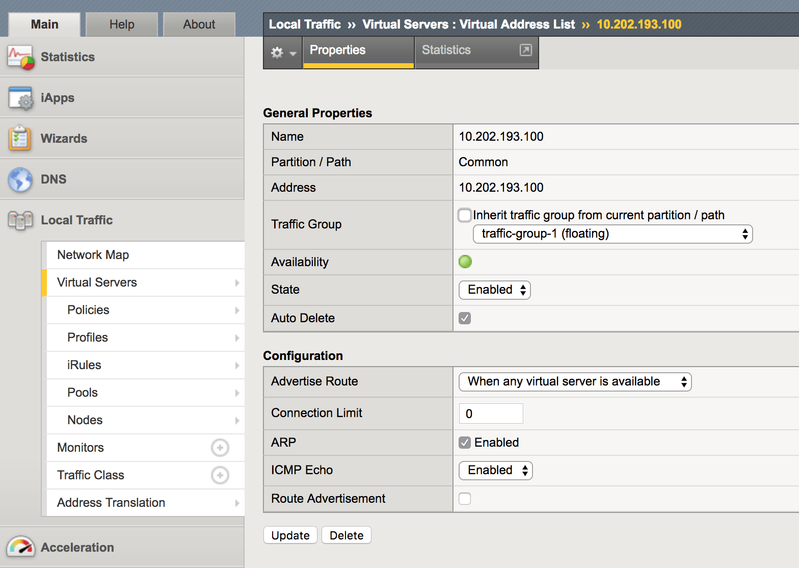
This is because we haven’t configured any routes to be advertised. F5 injects routes for virtual servers into the tmrouted as “kernel” routes, indicated by the K flag. However, this only happens after configuring virtual IP addresses with “Route Advertisement”. Go to Local Traffic > Virtual Servers > Virtual Addresses and select the virtual addresses that you want to advertise.
Note: virtual addresses are automatically created when creating a virtual server object. Multiple virtual servers using the same IP address (but different ports) only result in one virtual address. It also auto deletes itself if you remove the relevant virtual servers (by default).

After selecting the virtual address, check the Route Advertisement box. You can see the check box in the last field of the screenshot below. You can also see some other configurations relevant to route advertisement such as whether to advertise the route when any virtual server associated with this virtual address is available, or only when _all _of them are available. This is obviously dependent on your specific scenario.
After that is enabled, you can now see virtual server addresses in the IMI shell routing table.
bigip[0]>show ip route
Codes: K - kernel, C - connected, S - static, R - RIP, B - BGP
       O - OSPF, IA - OSPF inter area
       N1 - OSPF NSSA external type 1, N2 - OSPF NSSA external type 2
       E1 - OSPF external type 1, E2 - OSPF external type 2
       i - IS-IS, L1 - IS-IS level-1, L2 - IS-IS level-2, ia - IS-IS inter area
       * - candidate default

Gateway of last resort is 10.202.193.1 to network 0.0.0.0

K*      0.0.0.0/0 via 10.202.193.1, VL193-OUTSIDE
C       10.0.0.0/29 is directly connected, internal
K       10.202.30.0/24 via 10.202.191.1, VL191-INSIDE
C       10.202.191.0/24 is directly connected, VL191-INSIDE
C       10.202.193.0/24 is directly connected, VL193-OUTSIDE
K       10.202.193.100/32 is directly connected, tmm0
C       127.0.0.1/32 is directly connected, lo
C       127.1.1.0/24 is directly connected, tmm0
Great! We now see it in our LTM routing table, and we can see it is injected as a “kernel” route. Unfortunately, we will not yet see it in our router’s routing table.
Note: This feature is also called Route Health Injection (RHI).
Configure kernel route redistribution
Now that the routing table shows our virtual IP addresses as kernel routes, we need to redistribute them into BGP. On the IMI sh of TMSH, configure the following:
bigip[0](config)#router bgp 65001
bigip[0](config-router)#redistribute kernel
Verify virtual server route on router
Let’s verify that we see it in our router’s routing table now.
SDEL-SW-CORE#show ip route bgp
Codes: L - local, C - connected, S - static, R - RIP, M - mobile, B - BGP
       D - EIGRP, EX - EIGRP external, O - OSPF, IA - OSPF inter area
       N1 - OSPF NSSA external type 1, N2 - OSPF NSSA external type 2
       E1 - OSPF external type 1, E2 - OSPF external type 2
       i - IS-IS, su - IS-IS summary, L1 - IS-IS level-1, L2 - IS-IS level-2
       ia - IS-IS inter area, * - candidate default, U - per-user static route
       o - ODR, P - periodic downloaded static route, H - NHRP, l - LISP
       + - replicated route, % - next hop override

Gateway of last resort is 10.202.1.33 to network 0.0.0.0

      10.0.0.0/8 is variably subnetted, 46 subnets, 7 masks
B        10.202.193.100/32 [200/0] via 10.202.191.22, 00:03:50
Excellent! We are now successfully advertising our virtual server via BGP. Now let’s see what happens if the VIP becomes unavailable.
Verify route availability if virtual server fails
Note: For testing purposes, this must be simulated by force offline-ing the relevant pool members. Disabling the virtual server itself or the pool members does not trigger the Virtual Server to actually "fail" and pull the route advertisement.
“Force offline” the pool members of your testing virtual server. You could also actually fail the server itself and let the monitor check fail to test this more realistically.

Verify if the virtual server is now failed. Our testing VS is slitaz_http_pool, forgive the counter-intuitive naming. :)

Now let’s check that the route is no longer present on our router as a result of the failed virtual server.
RTR#show ip route bgp
Codes: L - local, C - connected, S - static, R - RIP, M - mobile, B - BGP
       D - EIGRP, EX - EIGRP external, O - OSPF, IA - OSPF inter area
       N1 - OSPF NSSA external type 1, N2 - OSPF NSSA external type 2
       E1 - OSPF external type 1, E2 - OSPF external type 2
       i - IS-IS, su - IS-IS summary, L1 - IS-IS level-1, L2 - IS-IS level-2
       ia - IS-IS inter area, * - candidate default, U - per-user static route
       o - ODR, P - periodic downloaded static route, H - NHRP, l - LISP
       + - replicated route, % - next hop override

Gateway of last resort is 10.202.1.33 to network 0.0.0.0
Note that no BGP routes are now present.
This, by default, will take up to 10 seconds to be reflected in the tmrouted. This can be viewed in TMSH as the query period. Note that the value only displays if it has been configured away from default.
list /sys db tmrouted.queryperiod
In order to modify this timer to have faster convergence to a failed virtual server, perform the following:
modify /sys db tmrouted.queryperiod value [period_in_seconds]
You can also delay the withdrawal of routes as a result of a virtual server status change using (to prevent flapping from effecting route advertisement):
modify /sys db tmrouted.rhifailoverdelay value [delay_in_seconds]
Obviously, the BGP config used was quite rudimentary as an example, but route-maps and other functions can be configured, as well.
References
This article was used as reference. I recommend reading through it for caveats specific to your situation, as well as confirming your BIG-IP software version has no specific considerations.